


The DSP Logger Expert, has the possibility of performing the signal analysis that can be taken from the condition monitoring panels of big machines.
While it is true that these condition monitoring equipments do show the displacement values from the proximity sensors, they do not have in every case the possibility of an analysis through spectral graphics, orbitals, bode or wave forms.
In these cases, the use of conventional tools that the DSP Logger Expert possesses and its appropriated cables, allow to get more analysis information, from these reliable condition monitoring systems.
How to obtain sensors information like Proximitor and Keyphasor with DSP Logger Expert?
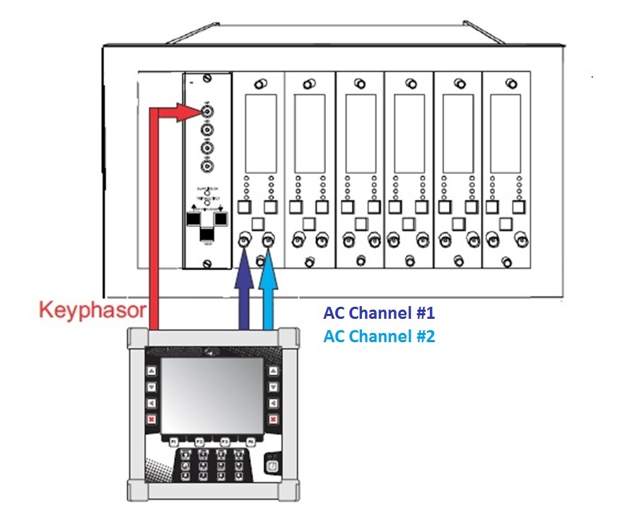
In the first place there should be two auxiliary
cables to connect the sensors to the CA entries
and a special cable to connect the Keyphasor
to the tachometer entry in the DSP Logger
Expert.
Then, there should be at least the Vibration Analyser module
and Phase Analysis module for a correct information and
measurements analysis.
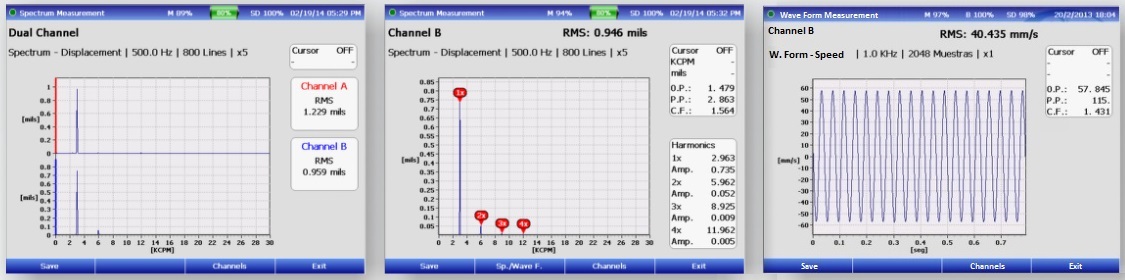
Analysis with spectrums and wave forms
With the analyzer module we can obtain the vibration, spectrums and wave forms values taken by these sensors. For this you need to go to the configuration screen, in the Variable field, then you simply need to select CA Amplitude, and in the Channel you need to select CA 1 (if the sensor is connected to Channel A) or CA 2 (if its connected to Channel B), then select the measurement type, for example: “spectrum”, and finally perform the measurement to be able to see the graphic and determine conditions of: balancing, misalignment, looseness, etc.
It’s important to keep in mind that previously to the measurement, it is necessary to configure the sensibility of the sensors that must be connected. In order to do that, you must enter from the main menu to the Utilities function and then Config Input, where the sensors must be registered indicating model and series number (not relevant data) and most importantly its sensibility and measurement unit (this data must be as accurate as possible, due to the fact that the measurement reliability depends on them) for example an usual data will be 8 mV/μm, then, in the AC channels, select the entered sensors and we are ready to perform the measurements.
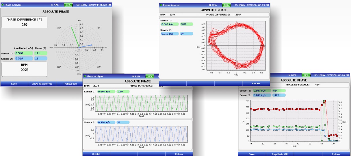
With the Phase Analysis module you can obtain the phase difference between two proximitor type sensors, with the possibility to see the wave form and the orbital generated by two sensors located at 90º one from the other. For this, as usual, you must select the CA Auxiliar option in the Variable field, and then proceed to perform the analysis in the usual manner.
It will also be possible to perform a rotor balance using as sensors entry the AC channels, and, instead of optic sensor, connect the Keyphasor to the tachometer entry, when entering to the balancing module, and before selecting balancing in 1 or 2 planes with the F1 key select CA Amplitude as variable and then proceed as an usual balancing.
